Logic Module
Each logic scheme represents a sheet containing block units. In the sheet it is possible to add several kinds of nodes, each one of them corresponding to a specific function in the server. The interaction of the node is defined by its connectors which are inputs and outputs of the node. Several nodes can be linked together by creating connections among the nodes. A connection is a link that starts from an output connector in a node and ends in an input connector.

Scheme management
The logic scheme can be managed with the following buttons in the toolbar:
Import It imports the block diagram contained in a XML file into the current logic scheme. This operation overwrites completely the logic scheme!
Export It exports the current logic scheme in an XML file so that can be used inside other logic schemes. This operation doesn't save the current logic scheme inside the Configurator but just exports it!
Save It saves the current logic scheme inside Configurator.
Close It closes the logic scheme editor window.
Simulation management
The simulation feature allows to predict and debug what will happen when the block diagram will be executed inside the Thinknx server. Inside Thinknx Logic Module there are two kinds of simulation: Offline Simulation and Online Simulation.
Offline simulation simulates the behavior of the server by executing the block diagram inside Configurator and showing in realtime the values passing by all inputs and outputs of the nodes. In this way the user keeps trace of the values due some input values.
Online simulation connects to Thinknx server and provides feedback regarding the execution of the block diagram directly inside the server.
Online simulation only works if the Configurator is in the same local network of the server. The IP needed for the connection corresponds to Local IP address specified in the System object.
The feedback provided while the simulation is running can be managed with some parameters by clicking the Sim. Settings button in the toolbar:

Force show value labels for all connectors During a simulation, when the value passing by a connector is updated, a box showing the value appears beside the connector. To force this box to always be shown during simulation, check this box.
Value updates fade timeout If the previous checkbox is unchecked, it indicates the time the update will be shown on the screen.
Nodes, Connectors and Connections
Create a node
To create a node, open the “Node Types Library” and drag the desired node into the sheet. For each node it is possible to edit its properties by clicking on it.

Edit a node
By selecting the node, the property grid gets populated with its properties, by editing them the behavior of the node will change.

Every connector in the node has its own properties to describe its behavior. To edit them, click on the connector and the properties will be displayed in the property grid.
It is possible to select multiple nodes by pressing the Shift key.
Delete a node

To delete a node, select it and press Del key, or click on the little X icon which appears by moving the mouse over the node. After the node has been deleted, all the connection associated to the node will be removed.
Create a connection between nodes
To build the block diagram, it is necessary to link the nodes among each other. To create a connection click and hold one connector in the node and drag the mouse until the connector of the destination node. Before releasing the mouse, if the connection respects the standard rules among nodes, a green check will appear near the destination connector.
Connections can be established ONLY between an output connector and an input connector belonging to different nodes.
One output connector can link to several input connectors but one input connector can link to just one output connector!

Data compatibility among nodes
There are no limitation in the creation of a new connection due to data compatibility, the incoming values will be automatically converted to the expected input type following these rules:
Bit to Number When a logic output (a bit) is connected to an analog input (a number), the system will convert the logic 0 (False) to 0 and the logic 1 (True) to 1.
Number to Bit When an analog output (a number) is connected to a logic input (a bit), the system will convert the analog value to a logic 0 (False) if it is equal to 0, and to a logic 1 (True) for all the other values.
String to Bit When a string coming from an input node is connected to a logic input, the system will convert the string to a logic 1 (True) only if the string is equal to 1 or to “true”.
String to Number When a string is connected to an analog input, the string value is converted into a number.
Gate connector

Except for input and output nodes, all the nodes can be enabled and disabled with the Gate connector. To show the Gate connector on the node, the Gate property on the node must be enabled.
When a node is disabled, the computation is not performed and no values are sent to the output connectors even if an input connector receives a new value.
By selecting the Gate connector it is possible to edit its properties which determine the behavior of the node:
Inverted gate If disabled, the node is enabled when the connector's value is 1 and disabled when the connector's value is 0. By enabling this property, the behavior will be inverted (0 = node enabled, 1 = node disabled).
Force output sending If enabled, when the node gets enabled, the values of all the output connectors are refreshed independently by the Output sending behaviour property of the corresponding output connector.
When the Gate property is enabled, if the Gate connector is not connected to any other node, the node is disabled by default. Otherwise, if the Gate connector is connected to a node but it is not receiving any value from the source of the connection, the node is still disabled.
The picture below describes the behaviour of the Gate in the node:

The scheme should be able to read values coming from the plant as the the inputs of the block diagram or just provide some constants in the logic.
There are several kinds of Input nodes that can be used for this purpose:
Constant Value

It represents a constant inside the block diagram. It can be a number, a bit or a string.
KNX Input

It represents an input coming from the KNX bus.
Sheet Input
System Status

It represents an input coming from a status of a System object in the Configurator. For example, a feedback coming from Sonos.
Output Connector
All the input nodes have only one output connector and the input value of these nodes will pass through it. In this connector it is possible to define the policy that will be used to forward the value to the connected nodes through the property:
Output sending behavior It indicates when the value has to be forwarded to the connected nodes.
’On result change’ indicates that the result is sent only when different from the previous one.
’When a new input telegram is received’ indicates that the result is sent whenever the server receives a value update from the source of the input.
During Offline Simulation it is possible to simulate the value updates by manually typing them in the toolbar panel.
Output nodes
The scheme generates one or more output values to send on the KNX bus, commands to perform, etc. The output nodes represent the kind of action to perform with these values.
There are several kinds of Output nodes that can be used for this purpose:
Command

It represents the command to be executed when a value on the input connector is received.
Trigger It determines the behaviour of the node for the command execution:
On trigger If selected, a new Trigger input connector is added to the node, which executes the command whenever the connector value is 1 (or 0 if the connector is inverted)
On parameter value change If selected and the parameters are input connectors of the node, whenever the value of an input connector is updated, executes the command
Command It is the command to execute. If the selected command has parameters, they are added to the property grid as new node properties, and for each parameter it is possible to assign a value or to make it become an input connector for the node so that the value for the parameter is dynamic.
KNX Output
It represents the KNX group on which the value will be sent.
Sheet Output
All the input connectors of output nodes have the following properties:
Analog nodes
The Analog nodes represent a collection of node which perform analog operations.
Comparator/2 Points Regulator

The Comparator node accepts numeric values for Input 1 connector and Input 2 connector and generates a pulse as the result of the comparison between the two inputs. If the difference between the two input values is greater than the value specified in the Threshold for ON property of the node, a logic 1 is sent to the Output connector. Instead, if the difference is lower than the value specified in the Threshold for OFF property, a logic 0 is sent to the Output connector.
When the the difference is among the two threshold values, the previous state of the output is maintained.
This node is really useful for temperature regulation because it acts as a 2 Points Regulator, preventing frequent switching of the output.

PID Controller
Pulse Width Modulator

The Pulse Width Modulator node converts an analog input into a pulse where the ON/OFF ratio depends on the modulated value of the Input connector.
The node computes the ratio of the Input value with the Input Min. property and the Input Max. property and applies it to the Period of the output pulse to determine the ON time.
The ratio is calculated at every expiration of the Period and thus it considers the actual value of the Input connector in that moment.

Ramp

The Ramp node increases or decreases in a linear way the value of the Output connector until it reaches the value of the Input connector. The linear increment consists of adding (or subtracting) to the Output a value represented by the Step size property every time interval specified by the Time step property.
The value of the Output can't go beyond the Input value, so the node reduces the step to adapt the output to the input.

Range Verifier

The Range Verifier node, given the analog value of the Input connector, checks if it is included between two threshold values, specified with the properties Threshold Min. and Threshold Max., and sends 1 to the Output connector if the condition is verified, otherwise 0.

Behaviour of Range Verifier
Threshold Filter

The Threshold Filter node, given an analog value on the Input connector, sends it to the Output connector if the value is included between the values specified by the two properties Threshold Min. and Threshold Max., otherwise it sends the value of the reached threshold.
It is possible to exclude one of the two thresholds by editing the Filter type property of the node.

Behaviour of Threshold Filter with Filter Type set to Minimum and maximum thresholds
Time-based Filter
Counter nodes
The Counter nodes, given an input (number or bit), perform a counting operation on the input and send it to the output.
There are several kinds of Counter nodes that can be used for this purpose:
Maintenance Counter

The Maintenance Counter counts the total time the Input connector value is 1 and forwards it to the Output connector whenever the Input receives a falling edge on the signal. The unit of measure of the time is defined through the Time UoM property of the node.
If the Reboot survive property of the node is enabled, the counter value is persistent which it means that it doesn't get lost when the server reboots and after the reboot, the counter increments the last saved value; otherwise, the counter value gets resetted every time the server reboots.
The Start Date output connector sends the last date and time the counter received a Reset signal.
When the Reset input receives 1, the counter gets resetted, Output goes to 0 and Start Date is updated, the counting will start again only after Reset goes back to 0.

Behaviour of Maintenance Counter
Up/Down Counter

The Up/Down Counter increases the counter whenever the Increment input receives a rising edge and it decrements the counter whenever the Decrement input receives a rising edge.
If the Reboot survive property of the node is enabled, the counter value is persistent which it means that it doesn't get lost when the server reboots and after the reboot, the counter increment/decrement the last saved value; otherwise, the counter value gets resetted every time the server reboots.
The Start Date output connector sends the last date and time the counter received a Reset signal.
When the Reset input receives 1, the counter gets resetted, Output goes to 0 and Start Date is updated; the counting will start again only after Reset goes back to 0.

Behaviour of Up/Down Counter
Statistic Meter

The Statistic Meter reads the numeric value of the Input connector and calculates:
Current day total on the Curr. Day output connector
Current week total on the Curr. Week output connector
Current month total on the Curr. Month output connector
Current year total on the Curr. Year output connector
Previous day total on the Prev. Day output connector
Previous week total on the Prev. Week output connector
Previous month total on the Prev. Month output connector
Previous year total on the Prev. Year output connector
The counted values are persistent, which it means that they don't get lost when the server reboots.
The Start Date output connector sends the last date and time the counter received a Reset signal.
When the Reset input receives 1, the counter gets resetted, all the outputs go to 0 and Start Date is updated, the counting will start again only after Reset goes back to 0.
Whenever the Data Request input connector receives 1, the node refreshes the values of the outputs.
To make the Statistic Meter operational the first time it is loaded into the server, it needs to receive 1 on the Reset input connector or on the Gate connector (if enabled).
Output connectors
All the output connectors of the counter nodes have particular properties to manage the policies to send the values:
Output sending behaviour The connector value will be updated depending on the following criteria:
On new value reception Whenever the node updates the value, it sends it to the connector.
After a fixed time interval The node sends the value to the connector at the expiration of a specified time interval, independently by the fact that the value has changed or not.
On over-threshold change The node will compare the latest computed value with the previous one, if the difference between the two values overcrosses a predefined threshold it will send it to the connector. The threshold represents the ratio between the gap of the two values and the previously stored value.
On over-threshold change and after time This option combines the advantages of both previously explained techniques. The node will send the value when over-threshold change occurs and, in any case, after a fixed time interval.
Store time interval Time interval to wait before the node sends the value to the connector.
Change percentage Minimum change percentage required to send the value to the connector. To be sent, the new value has to differ from the previous value more than the percentage applied to the previous value.
Logic nodes
Logic nodes represent all the operations to manipulate bits. Exept some special nodes, it is always possible to edit the number of inputs of the node with the property Number of inputs.
And

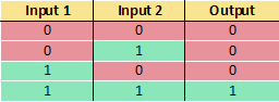
The And node sends 1 on the output only when all the inputs are 1.
Filter

The Filter node forwards to the output the value coming from the input connector follwing some policies determined by the following properties:
If

The If node evaluates the value of the input Condition, if it is equal to 1 sends the True value input value to the output, otherwise it sends the False value input value.
Latching Relay

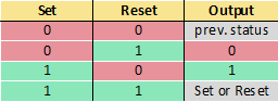
The Latching Relay node sends 1 to the output when the input Set is set to 1 and sends 0 to the output when the input Reset is set to 1. When both Set and Reset are 0, the previous state of the output is mantained.
The Behaviour property determines whether Set or Reset must be dominant when both of them are 1.

Behavior of node when Set input is dominant

Behavior of node when Reset input is dominant
Logic Matrix

The Logic Matrix, given some inputs determined by the Number of inputs property and some outputs determined by the Number of outputs property, forwards the value of a selected input to a selected output. The selection of inputs and outputs is decided by the value of two inputs, Input selector and Output selector.
The Data type property determines the inputs and outputs data type managed by the matrix; if it is set to 1 bit Boolean, the inputs and outputs are the standard connectors for all the logic nodes as explained here, otherwise the Inverted property on the connectors won't be available.
Input and Ouput selectors
These connectors have two properties to define their behaviour:
Default control value It indicates the default input/output with a number [0-255] representing the 0-base index of the input/output.
Update every control value If enabled in the Input selector, outputs will be updated for every value received by the Input selector. If disabled, outputs will be refreshed only when the selected input receives a new value or, if this property is enabled in the Output selector, when the Output selector receives a new value.
Nand

The Nand node is the opposite of the And node, sends 0 on the output only when all the inputs are 1.
Nor

The Nor node is the opposite of the Or node, sends 1 on the output only when all the inputs are 0.

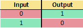
Not

The Not node accepts just one input, it inverts the value of the input.
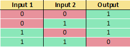
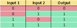
Or

The Or node sends 1 on the output when at least one input is equal to 1.
Pulse Relay

The Pulse Relay node sends 1 to the output when the input Set is set to 1 and sends 0 to the output when the input Reset is set to 1. When both Set and Reset are 0, the previous state of the output is mantained. Whenever the input Trigger receives a rising edge signal, Set and Reset are ignored and the output is toggled.
The Behaviour property determines whether Set or Reset must be dominant when both of them are 1.

Behavior of node when Set input is dominant
The Pulse Relay it is used to transform a pulse input in a toggle switch!
Set and Reset inputs are optional, if they are not connected to any other nodes, the Trigger input is the only input which controls the output.
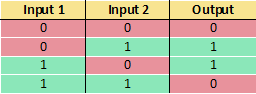
Xand

The Xand node sends 1 on the output only when all the inputs are equal.

Xor

The Xor node sends 1 on the output when the inputs don't have the same value.
All the input connectors of logic nodes have the following properties:
Trigger Whenever a new value is received on the connector, if this property is enabled, the node triggers the computation and sends the values to the output connectors.
Inverted input If enabled the connector inverts the received value. If the value on the connector is inverted, a red symbol appears beside the connector.
Output connectors
All the output connectors of logic nodes have the following properties:
Timer nodes
The Timer nodes represent time-based operations inside the scheme.
Continuous Pulse Generator

The Continuous Pulse Generator node, for all the time the value of the Gate connector is 1, generates pulses with the ON time specified by the Factor for ON property and the OFF time specified by the Factor for OFF property.

Behaviour of Continuous Pulse Generator
On/Off Delay

The On/Off Delay node, for every rising edge of the Input connector signal, generates a rising edge on the Output connector after a delay specified by the Factor for ON delay property. When the Input signal has a falling edge, the node generates a falling edge on the Output connector after a delay specified by the Factor for OFF delay property.
When the value of the Reset connector is 1, the node immediately sends 0 to the Output connector.

Behaviour of On/Off Delay
Pulse Train Generator

The Pulse Train Generator node, for every rising edge of the Input connector signal, generates a train of pulses on the Output connector with the ON time specified by the Factor for ON property and the OFF time specified by the Factor for OFF property. The number of sequential pulses to generate is determined by the Pulse number property.
When the value of the Reset connector is 1, the node immediately sends 0 to the Output connector.

Behaviour of Pulse Train Generator with Pulse Number = 2
Random Generator

The Random Pulse Generator node, for all the time the Gate connector value is 1, generates pulses with random times for ON and OFF.
The random time for ON will be included between Minimum factor for ON property and Maximum factor for ON property; the random time for OFF will be included between Minimum factor for OFF property and Maximum factor for OFF property.

Behaviour of Random Pulse Generator
Scheduled Pulse

The Scheduled Pulse node, if the Gate connector value is 1, generates a pulse at a precise time of the day.
The time is specified by the Scheduled Time property, the pulse generated has a period determined by the properties Factor for pulse duration and Time base for pulse duration.
Stairwell Lighting Switch

The Stairwell Lighting Switch node, when the Input connector value is 1, sends 1 to the Output connector and then starts a timer, at the expiration of the timer it sends 0 to the Output connector.
The timer is set to the time defined in the Time for ON property of the node and if the property Retriggerable is enabled, the timer restarts whenever the Input connector receives 1.
If the property Manual OFF is enabled, when the Input connector value goes to 0 the node sends 0 to the Output connector and automatically stops the timer; otherwise the expiration of the timer is the only condition to send 0 to the Output connector.
The Warning connector value goes to 1 before the timer expires until the Output connector is 1. The time for warning is specified through the Warning before OFF property.

Behaviour of Stairwell Lighting Switch
Stopwatch

The Stopwatch node measures provides two modalities to determine how it should start counting time which are specified by the Trigger policy property:
Switch The Stopwatch starts counting time when the Input connector value goes to 1, it pauses when the Input value goes to 0. Whenever the node pauses, it sends the time the Input value has been 1 to the Partial time connector and the total counted time to the Total time connector.
Toggle The Stopwatch starts counting when it receives the first rising edge on the Input connector, all the other times it receives a rising edge it sends the time passed between the current rising edge and the previous one to the Partial time connector, and the total counted time to the Total time connector.
When the Reset connector value is 1, the node stops counting the time and sends 0 to both Partial time and Total time, it will start counting again only after the Reset value goes to 0.

Behaviour of Stopwatch with Trigger policy Switch

Behaviour of Stopwatch with Trigger policy Toggle
Math nodes
The Math nodes represent all the arithmetical operation that can be performed inside the scheme.
Abs: It computes the absolute value of the given input value and sends the result to the output connector
Add: It computes the addition of
n input values and sends the result to the output connector
Average: It computes the arithmetic mean of
n input values and sends the result to the output connector
Division: It computes the division of two inputs and sends the result to the output connector
Logarithm: It computes the logarithm given two inputs, which represent base and argument of the logarithm, and sends the result to the output connector
Max: Given
n inputs, it sends to the output the maximum value among the inputs
Min: Given
n inputs, it sends to the output the minimum value among the inputs
Multiplication: It computes the multiplication of
n input values and sends the result to the output connector
Pow: It computes the exponentiation given two inputs, which represent base and exponent, and sends the result to the output connector
Remainder: It computes the division of two inputs and sends the
remainder to the output connector
Round: Given an input, it rounds the value to the closest integer and sends it to the output connector
Subtract: It computes the subtraction of
n input values and sends the result to the output connector
Scripting Node
Scripting Node
The scripting logic module allows users with basic programming knowledge to freely define operational logic.
To configure a script, it is necessary to write the code using the provided IDE to execute the algorithm.
The MainMethod is called by default when executing the logic module. It is possible to define additional input parameters by adding new parameters in the method signature:
public static object MainMethod(object parameter1, object parameter2, object parameterN)
To successfully complete the script execution, an output must be returned.
Example of an addition script
If multiple output values are required beyond the default function output, parameters can be defined that, in addition to serving as input, can also be used as output.
Example of return parameter 2 value
Logic Examples
Temperature Regulator

Example 1: Temperature Regulator
Using the Math Expression bloc and the function “Regulator”, it is possible to implement a regulation on an output given a setpoint and an actual temperature value. The two additional inputs in the expression are the “hysteresis” value, and the possibility to invert the result (1= inverted, 0= normal). The example shown in the picture above will send value 1 to Heat Valve and 0 to Cool Valve in case Setpoint > Actual, and value 0 to Heat Valve and 1 to Cool Valve in case Setpoint < Actual.


