Table of Contents
End User Manual
Click here to download the manual as PDF.
Table of Content
- 2. General Layout
- 2.2. Settings Interface3. General Functions
-
1. Introduction
This user manual is intended for end users who have Thinknx server installed at their home, office or other type of building.
It is only a guide on how to operate Thinknx UP Client application available on iOS, Android, Windows and Mac. Each supervision project is unique in terms of graphics and functionality, however, this guide offers an overview of the most common and used features allowing the user to easily navigate through the interface.
It is assumed that the Thinknx server installed is configured by an installer, system integrator or other professional figure and that the project is already deployed on the client device ( for more information on the creation of a supervision project, please refer to this page).
For more enquiries regarding the use of Thinknx products, our support team is available to answer tickets on www.thinknx.com/support.
2. General Layout
2.1. Project Interface
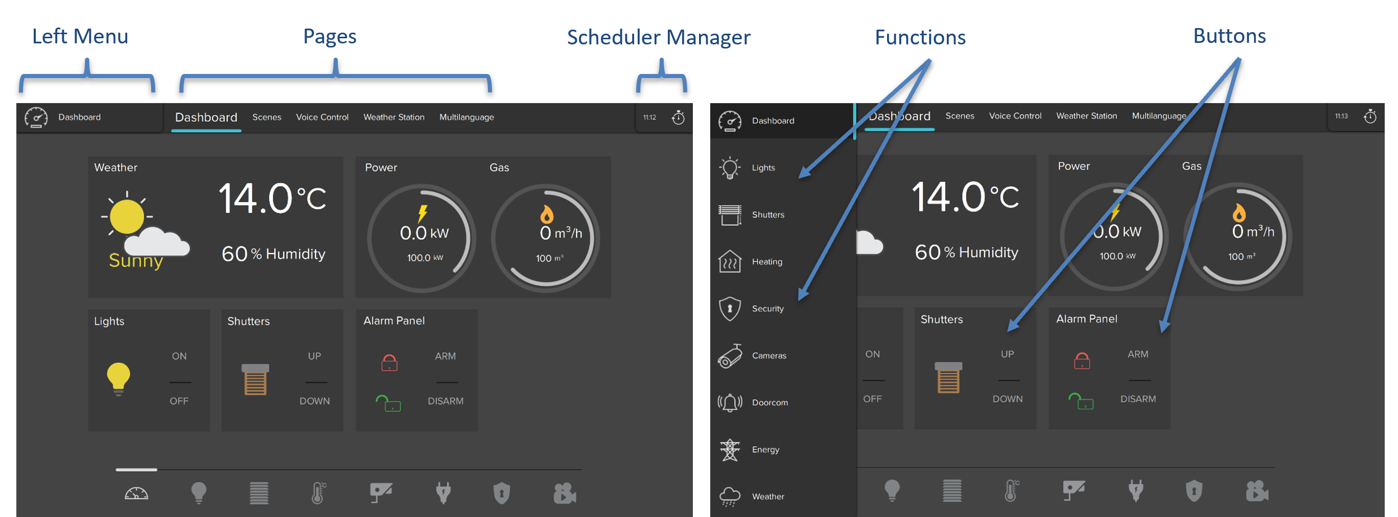
The project interface consists of a left menu holding the main functions created by the integrator. Each function contains a large number of pages which can be changed by swiping left/right or clicking on the title at the upper bar. The Scheduler Manager can be accessed by clicking on the clock icon at the top right corner of the project.
Figure 2: Project Interface
2.2. Settings Interface
To access the Settings page, open the left menu and scroll up to reach the “Settings” item.
Figure 3: Access to Settings
The settings page consists of the projects list located to the left, and the general settings of the project located to the right. These settings will allow the user to modify the appearance, change volumes, language and even update firmware if applicable. At the bottom of the page, multiple buttons are available to download a new project onto the client device using different methods (locally, through serial number and Cloud password, or using a QR code, if applicable).

Figure 4: Settings Interface
2.2.1. Add a Project
Adding a project can be done via two methods:
- Using the local network This can only be done in the presence of the installer or any person who is able to open the project file with the Thinknx Configurator. The URL provided by this person can be entered inside the corresponding field after clicking on the “PC” icon in the client application followed by port 5050. The project will then be downloaded using the same network as the Thinknx server.
Figure 6: Download project locally
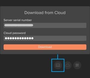
- Using Thinknx Cloud This can be done by the client without the presence of the installer. However, the installer will have to provide the client with the correct serial number and password. The client can click on the “Cloud” icon, enter the serial number and password, and click on Download. Once the download is completed, the project will show in the list to the left.
Figure 7: Downloading project from Cloud
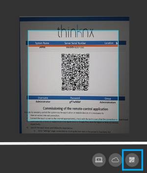
- using a QR Code The client can easily download the project by clicking on the “QR Code” icon and scanning a QR code shared by the installed by email/pdf. A permission should be granted to the Thinknx application to access the device's camera.
Figure 8: Downloading project by QR code
2.2.2. Authenticate Clients
When opening a recently added project for the very first time, an authentication process takes place between the client's device and the Thinknx server. Authentication can be done in two ways:
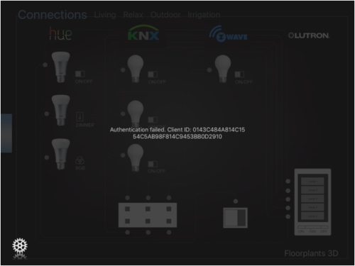
- Using the local network If the project has been added locally by the installer, the client will get a notification when opening the project stating that the “authentication failed”. The installer in that case must add the device ID of the client to the authenticated clients list inside the server.
Figure 9: Client Authentication 1
- Using Thinknx Cloud When the project has been downloaded from Thinknx cloud by the client, they will be prompted for a username and password the very first time they attempt to open the project. Both username and password shall be provided by the installer.
Figure 10: Client Authentication 2
- Using OTP Another way to authenticate when the project has been downloaded from the Cloud is by entering a one-time password (OTP) generated by the admin user. The popup window can be toggled to enter the OTP, which is valid to be used for 2 hours only.
Figure 11: Client Authentication 3
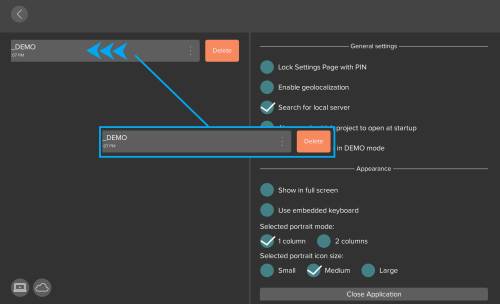
2.2.3. Delete a Project
To delete a project, slide project name to the left and click on “Delete”.
Figure 12: Settings Interface
2.2.4. General Settings
Under General Settings, it is possible to enable the below options:
- Lock Settings page with PIN The settings page can be locked with a pin code, allowing the users with access to the pin code to open the page from inside the project.
- Enable geolocalization If the user is managing more than one project (multiple houses), it is possible to automatically switch from one project to another by enabling the geolocalization. The nearest project is suggested based on the current location of the user.
- Search for local server When enabled, Thinknx will try to connect to the local IP address of the server before it attempts to connect through the Internet. It is useful when the client is inside the house and not accessing the project remotely.
By leaving “Search for local server” unchecked, the app will always be able to automatically detect if the client is connecting locally or remotely. It is only used in some cases where local connection is not established, but might cause delays when attempting to connect remotely without removing the option.
- Always ask which project to open at startup in case multiple projects are managed by the user.
- Open the projects in DEMO mode When enabled, the client will not establish a connection with the server and the project will open as DEMO.
Figure 13: General Settings
2.2.5. Advanced User Settings
Figure 14: Advanced Settings
When the client using the Thinknx UP application is configured to be Admin by the integrator, additional functions can be unlocked by accessing the Advanced Settings window:
- Change project language: permits to change the project into another language, as configured inside the Configurator. The change applies on the local device only.
- Share project: permits to generate a QR code to share with other users wanting to download the project.
- Manage Clients: permits to view and manage all the clients already authenticated with the server. The administrator can delete, add, and edit the users. Users can also be temporarily deactivated, or only allowed to access the application within a pre-defined time slot.
Figure 15: Manage Clients
- Manage Passwords: permits to change the different passwords used inside the project, for example, the password for cameras, intercom, etc. The new passwords set will be used instead of the ones configured inside the configurator and uploaded to the server and clients. The new passwords will not be replaced on each upload.
3. General Functions
3.1. Lighting
3.1.1. Switch
To control a simple ON/OFF light, a click on the corresponding icon will either send the toggled command instantly, or open a popup window to choose the command to be sent.
Figure 16: Switch
it is possible for the programmer to enable a chrono-switch, allowing the user to configure a weekly schedule for the light. The user can also copy the schedule and paste it to another one.
Figure 17: Switch Schedule
3.1.2. Dimmer
To control a dimmer, a click on the corresponding icon will open a popup allowing the user to send an ON/OFF command or choose the dimming value by moving the slider around the buttons.
Figure 18: Dimmer
it is possible for the programmer to enable a chrono-switch, allowing the user to configure a weekly schedule for the light. The user can also copy the schedule and paste it to another one.
Figure 19: Dimmer Schedule
3.1.3. RGB
To control an RGB light, a click on the corresponding icon will open a popup allowing the user to select the color from the color wheel and control the brightness by using the slider.
Figure 20: RGB
When using the RGB button, clicking on the settings icon at the bottom right corner of the popup will open an additional window. The user can save their favorite colors by clicking the “+” button. The start button will play a sequence of the saved colors. It is possible to select between random/ordered playing mode, and change the time interval between the colors during the sequence.
To delete the preset colors, simply long press on any of the presets. An X icon will show on all presets allowing the user to select the colors to be deleted.
Figure 21: RGB Settings
If supported, it is also possible to control the temperature of the white channel and change its brightness. To access this window, click on the top right icon in the color wheel window.
Figure 22: White Temperature
3.2. Motorization
3.2.1. Shutter
A shutter icon consists of a vertical slider allowing the user to change the shutter height value. The user can also click on the Up/Down buttons under the slider and the Stop button when needed.
Figure 23: Shutter
3.2.2. Blind
For blinds, the icon will have extra buttons to control the rotation of the louvres to allow more or less light into the room. The user can either operate the louvres using the slider or the buttons underneath.
Figure 24: Blind
3.3. Climate
3.3.1. HVAC
An HVAC icon, when clicked, holds the below functions:
- An On/Off button at the top right corner to control the machine.
- A slider to change the setpoint of the room.
- An indicator of the setpoint value at the center.
- Four buttons around the indicator to change the modality between Heat, Cool, Dry, Fan.
- Two buttons at the bottom of the icon to change the fan speed.
When the popup window is closed, the icon will indicate the status of the machine, the mode selected, setpoint, and fan speed.Figure 25: HVAC
3.3.2. Thermo Comfort
A Thermo Comfort icon can be one of two types:
- Type 1 Control of the setpoint is done manually using the slider or the chrono thermostat schedule.
- Type 2 Control of the setpoint is done by selecting between Comfort, Standby, Night and Frost protection mode, or the chrono thermostat schedule.
Type 1
- Read the actual room temperature on the top left corner of the popup.
- Change the setpoint by selecting the manual mode (hand icon) and using the slider.
- If chrono-thermostat is enabled, click on settings to program the daily temperature settings per hour.
Figure 28: Chronothermostat
Type 2
- Read the actual room temperature on the top left corner of the popup.
- Change the setpoint by selecting the desired mode (Comfort, Standby, Night, Frost Protection) or using the slider.
- If chrono-thermostat is enabled, click on settings to program the daily mode settings per hour.
Figure 29: Chronothermostat 2
3.4. Scene
When accessing the Scene icon, the user is able to:
- Record actions in the scene.
- Access the actions list recorded.
- Rename the scene.
- Launch recorded scene.
Figure 30: Scene
When recording a scene, a red frame will appear around the interface allowing the user to browse through the pages and click on the buttons to be included in the scene.
If the users do not wish to send the commands to the bus while recording, they can click on the bottom right corner icon to enable/disable this feature.
Clicking on the bottom left corner of the screen will save and exit the recording mode.Figure 31: Scene Recording
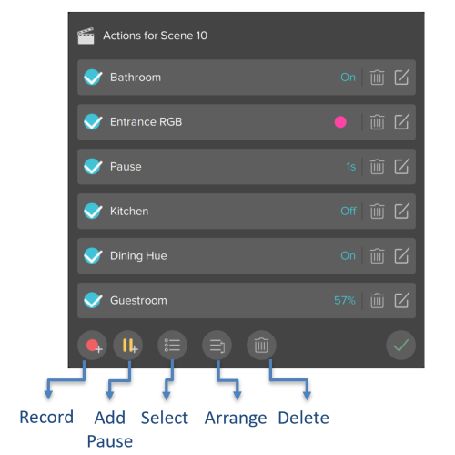
When clicking the Actions button, it is possible to:
- Record additional actions in the scene.
- Add a pause in between actions.
- Select multiple actions.
- Re-arrange the order of the actions.
- Delete one or more actions.
When recording additional actions, the red frame will appear again around the interface to allow the user to browse through the pages and click on the buttons to be included in the scene. Once finished, the user should click on the bottom left button (red circle) to save the changes.
Figure 32: Scene Actions
3.5. Scheduler Manager
Clicking on the Scheduler Manager icon at the top right corner of the application will open up a window to view/edit/create time schedules.
For each schedule it is possible to:
- Edit the schedule by clicking on the schedule name.
- Delete the schedule by clicking on the bin icon to the left side of the schedule.
- Access the actions list by clicking on the list icon next to the Delete button.
For more information regarding the actions list, refer to section 3.6. Scene.
Figure 33: Scheduler Manager
When adding a new schedule, the below functions are available to edit:
- Change schedule name.
- Switch between Simple and Advanced view mode.
If Simple mode is selected, the user will be able to:
- Define the time of day to launch the schedule.
- Select the days of the week to launch the schedule.
If Advanced mode is selected, the user will be able to:
- Define the date to launch the schedule.
- Trigger the schedule by time or sun event.
- Configure the Repeat function.
Figure 34: Adding a Schedule
3.6. Intercom
When using the intercom, regardless of the door unit installed, the user is able to:
- Receive a call on Thinknx Envision or Thinknx application whenever the door rings.
- Answer/Reject call.
- View the camera if available.
- Open door.
Figure 35: Intercom
When accessing the Settings page, it is possible to:
- Choose a ringtone.
- Change microphone volume.
- Enable/disable the use of ringtone in project.
Figure 36: Intercom Settings
3.7. Security
When a security system is integrated with Thinknx, the user has access to the system keypad and can use the security code to Arm/Disarm the system.
Figure 37: Security Panel
It is also possible to view the status of all the sensors installed and get notification when they are in an Alarm state.
Figure 38: Security Sensors
3.8. Irrigation Panel
With the irrigation function, it is possible for the user to:
- Run/Stop different irrigation zones independently.
- Create a program to automatically control the irrigation zones.
- Create a weekly time schedule for the program.
- Start/Stop the irrigation program.
- Enable/Disable the weekly schedule.
- Monitor the current and next program running as well as the zone being watered.
Figure 39: Irrigation Panel
When creating an irrigation program, such as the Morning program, the user can add the zones and easily input the start and finish time of the irrigation for each zone.
Figure 40: Irrigation Program
Once the program is created, it can be added to a weekly schedule by selecting the days of the week and configuring the timing per day.
Figure 41: Irrigation Schedule
Manage Via Vai
Once the project has been uploaded, after configuration there are two ways to manage the creation of new codes related to roles:
- Through the Thinknx server web pages
- Through the application if the user is set as Admin.
Option 1 - Web Page
Once the Thinknx project has been uploaded to the server, codes shall be generated by the Manager when needed using the server's web page.
- After logging in, go to Server–> Access Control.
- Click on “Generate new code” to view the new code.
- Assign a role to this code. The list will show all the roles added inside the project.
- Configure a time range for this code's validity.
- Save the code. A new entry will show in the table above with the added information. The admin will be able to edit this entry or delete it altogether.
- To allow direct access to the Access Control page, the Manager can use the link below, making sure to fill the proper IP address and password for the server: http://localhost:5051/login.html?login=login&direct_login&username=service&password=password&redirect=access_control_s.html
Option 2 - Through Thinknxup
Preliminary Steps The user must be enabled as a system administrator.

- To do this, access the server's web page.
- Go to Server - License & Code.
- Select the user in question and check the Admin option.
Application
Open the access control page
- Open the dropdown menu.
- Next to Settings, there are three dots.
- Select the dots.
- A menu will appear.
- Access Control Management.
Create a New User
- Press the “+” button at the bottom right of the new pop-up.
- Name: Enter the name of the user to assign the code to.
- Enable: To enable or disable the code as needed.
- Role: Assign the role associated with the doors they can open, created in the configuration by the system integrator.
- Pin Code: Generate the code.
- Enable if needed Validity Interval.
- Enable if needed Scheduling.
